Most spec sheets make the choice between a single-acting and a double-acting pneumatic actuator look like a checkbox. You pick spring return or you don't, you pick a torque value off a table, and you move on.
Then the compressor trips at 2 a.m., and everyone finds out whether that checkbox was actually a good decision.
The difference between the two architectures is not cosmetic. It shows up in the required air pressure, in the usable torque, in how the actuator behaves when air is lost, and — most importantly — in which direction a valve fails. This article walks through the real differences, using two actuators from Miller's MS Series as working examples: the MSD45 double-acting quarter-turn pneumatic actuator and the MSR045 single-acting (spring-return) quarter-turn pneumatic actuator.
How the Two Pneumatic Actuator Designs Actually Move
Both units share the same basic drivetrain. A piston travels inside a cylinder, its rack teeth turn a pinion, and the pinion turns the valve stem through 90°. What differs is what pushes the piston back on the return stroke — air, or a spring pack.
Double-acting (MSD45)
Air is admitted to one side of the piston to open, and to the opposite side to close. There are no springs in the housing. Output is symmetric: the actuator produces roughly the same torque in both directions, and it needs air for both strokes.
Single-acting, spring return (MSR045)
Air is admitted to one side only. That air compresses a spring pack while it drives the piston. When supply pressure drops, the stored spring energy drives the piston back and brings the valve to its preset position. The MSR045 ships with a 10-spring pack, and the number of springs can be changed to adjust output torque.
That single mechanical difference cascades into everything else.
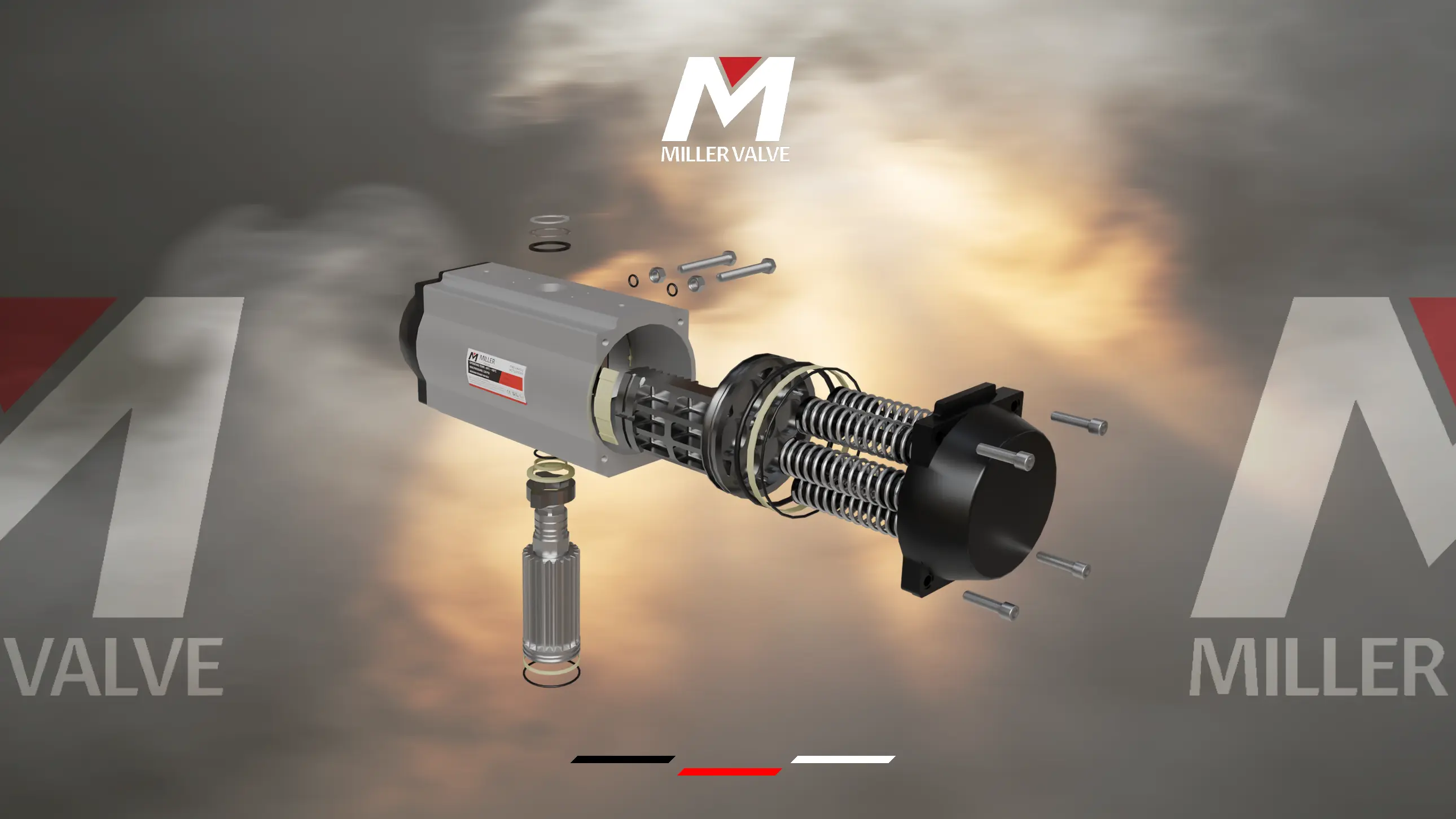
Torque, Air Pressure, and the Pneumatic Actuator Sizing Trap
This is where most field problems start, so it is worth being precise.
Because a spring-return unit must compress its springs with the same air supply that moves the valve, its minimum operating pressure is higher than that of a double-acting unit in the same frame size. The published ranges make the point:
| Parameter | MSD45 (double-acting) | MSR045 (single-acting) |
|---|---|---|
| Air supply range | 2.5–8.0 bar (36–116 psi) | 4.5–8.0 bar (65–116 psi) |
| Output torque | 3.6–11.6 N·m (32–103 in·lb) | 8.2–16.8 N·m (73–149 in·lb) |
| Springs | None | 10 (adjustable) |
| Fail behavior on air loss | Holds last position | Returns to preset position |
Two things in that table get misread constantly.
First, the torque number is not one number. A spring-return actuator has an air stroke and a spring stroke, and the two produce different torque. The air stroke has to overcome the process load and compress the springs, so it carries the larger figure. The spring stroke produces whatever the spring pack can deliver, and that value falls as the springs extend. If the spring stroke torque drops below the torque the valve needs to seat, the valve will close — just not all the way. Nothing looks broken. The position indicator still reads closed.
Second, the minimum pressure is a hard floor, not a recommendation. At 4.5 bar the MSR045 is at the bottom of its range. Supply it with 4.0 bar and two things can happen: the springs may not fully compress on the air stroke, and the spring stroke loses force it was counting on. Both are silent until the moment you need the actuator to do the one job it was bought for.
The right way to verify this is to compare the actual torque curve against the valve's required break and seat torque at the actual supply pressure available at the actuator — not at the compressor discharge. Line losses, dryers, filters, and long tubing runs all take their cut.
Two international standards frame that verification. EN 15714-3:2022 (Industrial valves — Actuators — Part 3: Pneumatic part-turn actuators for industrial valves — Basic requirements) covers actuator test conditions, torque ratings, and the performance data a supplier is expected to publish. For control valves, the sizing relationships are defined in IEC 60534-2-1:2011 (Industrial-process control valves — Part 2-1: Flow capacity — Sizing equations for fluid flow under installed conditions), the reference most engineers reach for when the actuator has to move against a known differential pressure. Read together, they answer the two questions that matter: what torque the actuator can actually deliver, and what torque the application actually demands.
What Fails, and What It Takes to Fail It
Both architectures fail for understandable reasons. The thresholds are the part worth memorizing.
Seal and diaphragm temperature limits
Actuator seals rarely fail because of hours in service. They fail because of temperature — usually at the two extremes of the day, not at the design point.
| Material | Typical service range | Fails by | Notes |
|---|---|---|---|
| NBR (nitrile) | approx. −20 to +100 °C | Hardens below the low limit and stops sealing; embrittles and cracks at the high end | Standard seal material on both MSD45 and MSR045 |
| FKM / FPM (fluoroelastomer) | approx. −20 to +200 °C | Compressive set at sustained high temperature | Optional on both models |
| Silicone (VMQ) | approx. −60 to +200 °C | Poor resistance to many hydrocarbon fluids | Optional; best for cold service |
| PTFE-coated sealing surfaces | Broad range | Cold flow under sustained load | Used as a coating, not a sealing element |
These are the ranges published by elastomer manufacturers and they move with compound. Treat them as planning limits and confirm the exact figure with the supplier before writing it into a specification.
Machine-air contamination
Seals are also destroyed gradually by what comes down the air line. Moisture carries compressor oil into the seal interface; particulates act as lapping compound on every stroke. The MSR045 lists NBR as standard with optional high- and low-temperature compounds, but no seal material survives wet, oily instrument air for long. Air quality is defined in ISO 8573-1 (Compressed air — Part 1: Contaminants and purity classes); a plant that does not know its own dew point class does not know its actuator's real service life.
Spring fatigue
This is the failure mode unique to spring-return designs, and the quietest one. Springs are compressed on every actuation. Over enough cycles, and faster at elevated temperature, they relax. In the MSR045 the springs are pre-compressed during assembly, and output torque depends on how many are installed. Once they take a set, the spring stroke torque drops, and the failure presents as an incomplete closure — not as a dead actuator.
MSD45 dosen't has a spring, the design sidesteps this entirely; what it cannot sidestep is that on air loss it stays exactly where it was.
Stem and coupling damage from over-torquing
Applying an actuator with more torque than the valve stem or seat can absorb bends stems and damages seats. The interfaces involved are standardized, which means they can be checked: ISO 5211:2026 (Industrial valves — Part-turn actuator attachments) defines the mounting flange dimensions and torque ratings, DIN 3337 defines the drive coupling dimensions, and VDI/VDE 3845 defines the NAMUR accessory interface on top. Both actuators here conform to NAMUR, ISO 5211, and DIN 3337 on the output shaft, and both use VDI/VDE 3845 at the top for limit switches and positioners.
One more standard belongs in this list. When a spring-return actuator is specified to close a valve against flow, the valve's seat tightness is part of the fail-safe claim. ISO 5208 (Industrial valves — Pressure testing of metallic valves) defines the leakage rate classes used to state that tightness, and it separates soft-seated from metal-seated expectations — a distinction that matters because the two seat types behave very differently as the spring runs out of force near the closed position.
Solenoid and accessory failure
Both models accept a NAMUR direct-mount solenoid valve. The mechanical interface is governed by VDI/VDE 3845 (mounting of accessories on part-turn actuators), while actuator-level requirements — including test and marking provisions — sit in EN 15714-3. On the air side, the NAMUR recommendation NE 005 addresses control air supply quality and interface practice.
Structural thresholds
The MSD45 uses an extruded aluminum body with hard anodizing and PTFE coating, die-cast aluminum end caps, a one-piece forged nickel-plated alloy steel output shaft, and cast aluminum hard-anodized pisto Aluminum and carbon steel are the wrong materials ns. The MSR045 uses the same body architecture with stainless steel fasteners.for aggressive chemical atmospheres and washdown service without additional protection. Companies that specify these actuators for caustic or chloride-rich environments are trading capital cost for a maintenance program.
Material and Parameter Comparison
| Item | MSD45 (double-acting) | MSR045 (single-acting) |
|---|---|---|
| Cylinder body | Extruded aluminum, hard-anodized + PTFE coating | Extruded aluminum, hard-anodized + fluoropolymer coating |
| End caps | Die-cast aluminum, anodized hardened + metallic polyester coating | Die-cast aluminum, anodized + metallic polyester coating |
| Pistons | Cast aluminum, hard-anodized | Cast aluminum, hard-anodized |
| Output shaft | Nickel-plated alloy steel, one-piece forged (stainless optional) | Nickel alloy steel, one-piece forged |
| Seals | NBR standard; FKM or silicone optional | NBR standard; high/low-temperature options |
| Fasteners | Stainless steel | Stainless steel |
| Air ports | G1/8 in., NAMUR | NAMUR |
| Travel adjustment | ±5°, dual independent stops | ±5°, dual independent stops |
| Standards (shaft) | NAMUR, ISO 5211, DIN 3337 | NAMUR, ISO 5211, DIN 3337 |
| Top accessory interface | NAMUR | VDI/VDE 3845 (NAMUR) |
The practical takeaway: the two actuators are close cousins mechanically. The material differences are minor. The behavioral differences are not.
Where Each Design Should Not Be Used
Honest boundary conditions matter more than feature lists.
-
Do not specify double-acting where the process requires a defined failure position: If the process safety review says the valve must close on air loss, a double-acting actuator without an accumulator, trip valve, or mechanical spring cannot deliver that. It will hold position, and holding position is a specific outcome, not a default safe state.
-
Do not specify spring-return where the air supply cannot reliably hold above the minimum: A spring-return actuator on a marginal header is worse than a double-acting one, because it invites false confidence: the valve moves, the indicator reads correctly, and the fail-safe function is quietly compromised.
-
Do not use either design in ambient temperatures outside the seal compound's range: Below the NBR low limit, seals harden. Above its high limit, they take a set and crack. Neither happens with a warning.
-
Do not use aluminum-bodied actuators in aggressive chemical or washdown service without confirming compatibility: These are general-purpose industrial actuators, not corrosion-resistant specials.
-
Do not use either for very high cycle rates or continuous modulating duty without checking the cycle life rating: Rack-and-pinion pneumatic actuators tolerate intermittent duty well; high-frequency modulating service accelerates seal and bushing wear and, on spring-return units, spring relaxation.
-
Do not assume a positioner fixes a torque problem: A positioner controls where the actuator goes. It does not add force.
Comparing the Failure Boundaries of Actuated Quarter-Turn Valves
The actuator is only half the assembly. Which actuator makes sense depends on what the valve itself demands.
| Valve type | Typical seating behavior | Torque demand | Best-fit actuator and why |
|---|---|---|---|
| Ball valve, floating (soft seat) | Low break torque, low running torque | Lowest of the group | MSD45 double-acting is usually sufficient; spring return only if the process requires a defined failure position |
| Ball valve, trunnion-mounted | Moderate, rises sharply at seat contact | Moderate to high | Double-acting preferred for torque headroom; spring-return where fail-close is mandatory |
| Butterfly valve, concentric (rubber-lined) | Very high break torque; rises steeply near closure | High relative to size | Double-acting with generous margin; spring-return needs careful sizing of the spring stroke |
| Butterfly valve, double-offset / high-performance | Higher break, lower running; sensitive to temperature | High | Double-acting, or spring-return only with verified spring-stroke torque at minimum supply pressure |
| Butterfly valve, triple-offset (metal seat) | Highest break torque; interference fit at seat contact | Highest | Double-acting with substantial margin; spring-return requires a torque analysis, not a table lookup |
Two conclusions follow from this. First, seat design drives torque demand far more than valve size does — a rubber-lined butterfly valve can demand more torque than a much larger soft-seated ball valve. Second, the harder the valve seats, the more dangerous a marginal spring pack becomes, because the spring stroke is weakest exactly when the valve meets its seat.
A Field Case
A municipal water treatment plant replaced a set of valve actuators as part of a controls upgrade. The new actuators were spring-return units on butterfly valves serving filtration backwash lines. Everything passed commissioning. Operations verified open and closed positions repeatedly, and the valves cycled cleanly for several months.
The problem surfaced during a compressor maintenance shutdown. When plant air dropped, several backwash valves did not fully close. Operators found the issue by accident, when turbidity readings shifted on a line that should have been isolated.
Investigation found a pressure problem, not an actuator defect. The plant air system delivered about 4.0–4.5 bar at the compressor discharge. After the dryer, filters, and roughly 60 meters of tubing to the farthest valve gallery, static pressure at the actuators measured near 3.8 bar. The spring-return actuators on those valves required 4.5 bar minimum. They had been operating in a state where the springs were never fully compressed and the spring stroke never developed its rated closing torque. During normal operation, small differential pressures kept the valves looking closed. When the valves actually had to seal, they could not.
Two fixes were applied: the air system was upgraded with a dedicated receiver and regulator for the actuator header, and the torque documentation for each valve was rewritten to list air stroke torque and spring stroke torque separately at the verified minimum supply pressure.
The lesson is not that spring-return actuators are unreliable. They are not. The lesson is that the fail-safe function lives in the spring, and the spring lives on the air supply. A plant that tracks compressor discharge pressure instead of pressure at the actuator has measured the wrong number.
Choosing the Pneumatic Actuator Type: The Questions That Matter
Strip away the sales language and the choice comes down to four questions:
-
What must the valve do when air is lost? If the answer is "go to a defined position," the architecture is spring return. If the answer is "stay where it is," double-acting is acceptable — provided the process is safe in that state. If the answer is "we are not sure," that is a process safety question, not a purchasing question, and it needs to be answered before anything is ordered.
-
What is the actual supply pressure at the actuator? Measure it, do not assume it. Then compare it against the manufacturer's torque table at that pressure, in both stroke directions for spring-return units.
-
What torque does the valve need, and in which direction?Break torque and seating torque are different numbers. So are air stroke and spring stroke.
-
What is the temperature at the actuator, not at the pipe? A valve in a heated enclosure with a warm body is not the same environment as the actuator bolted on top of it in a cold gallery.
The MSD45 and MSR045 share a mounting standard, a drive coupling standard, and an accessory interface — which means they are frequently interchangeable on the same valve. The mounting is not the decision. The failure behavior is.
Standards and References
All standards cited below are international (ISO / IEC) or internationally applied industry standards, and all are current at the time of writing.
-
ISO 5211:2026 — Industrial valves — Part-turn actuator attachments (mounting flange dimensions and torque ratings). This edition superseded ISO 5211:2017; projects specifying the older edition should confirm which one their supply chain is working to.
-
EN 15714-3:2022 — Industrial valves — Actuators — Part 3: Pneumatic part-turn actuators for industrial valves — Basic requirements (actuator test conditions, torque ratings, published performance data)
-
IEC 60534-2-1:2011 — Industrial-process control valves — Part 2-1: Flow capacity — Sizing equations for fluid flow under installed conditions
-
ISO 5208 — Industrial valves — Pressure testing of metallic valves (leakage rate classes, soft-seated vs. metal-seated)
-
ISO 8573-1 — Compressed air — Part 1: Contaminants and purity classes
-
VDI/VDE 3845 — Mounting of accessories on part-turn actuators (the NAMUR accessory interface)
-
DIN 3337 — Drive coupling dimensions for part-turn actuators
-
NAMUR NE 005 — NAMUR recommendation on control air supply interfaces
-
Miller MS Series product documentation: MSD45 double-acting quarter-turn pneumatic actuator and MSR045 single-acting quarter-turn pneumatic actuator
Seal and elastomer temperature ranges are typical industry values published by material suppliers and vary by compound; confirm exact limits with the actuator manufacturer for the specific configuration ordered. Actuator performance figures above are drawn from published Miller MS Series specifications.
Reviewed by Su, Senior Valve Commissioning Engineer (20 years of field commissioning experience).