When a three-way ball valve switches from one media source to another, the immediate question is usually simple: can the valve move from position A to position B? The more important question is what happens during the movement. Which ports are connected while the ball rotates? Are two incompatible fluids exposed to each other for a fraction of a second? Can pressure transfer into a closed line? How much of the previous medium remains in the ball passage, cavity, or seat area?
These details affect product purity, process safety, and valve service life. Two DN50 three-way ball valves may both appear to satisfy the same switching task on a static P&ID, but an L-port design and a T-port design can behave very differently during the actual changeover.
This article is written for plant engineers, EPC contractors, OEMs, and maintenance teams who need to evaluate media changeover as a dynamic process. It focuses on three questions:
- What happens inside different three-way ball valve flow paths while the ball rotates?
- How do fluid properties amplify the effects of those flow paths?
- What sequence, actuator configuration, and verification methods are needed to control the risks?
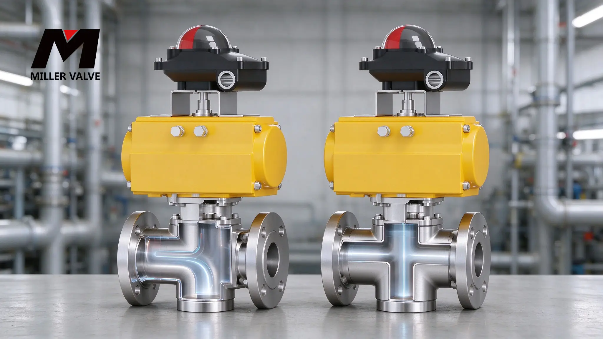
1. Flow-Path Design Changes Four Changeover Variables
A three-way ball valve does more than define which two or three ports are connected during normal operation. Its flow path also determines the transient states, residual volume, and pressure relationships during changeover.
| Changeover Variable | Typical L-Port Behavior | Typical T-Port Behavior | Effect on Media Changeover |
|---|---|---|---|
| Port connection | Connects two adjacent ports while the third is closed | Can connect two ports or all three ports | Determines mixing, backflow, and cross-contamination potential |
| Intermediate position | May temporarily isolate one or two paths | May pass through several two-port or three-port states | Determines pressure disturbance and contact time between media |
| Residual volume | Fluid can remain in the ball passage, seat area, and cavity | Fluid can remain at the three-port junction and inside the ball passage | Determines purge difficulty and contamination risk |
| Pressure transfer | The closed port normally stays outside the active flow path | Pressure can transfer between all three ports when connected | Determines whether a low-pressure line can be overpressured or reversed |
A correct static flow path does not guarantee a safe dynamic changeover. When two media must not contact each other, the complete rotation from the starting position to the final position must be reviewed.
1.1 A 90-Degree Stroke Is Not Instantaneous
Three-way ball valves are often described as 90-degree fast-switching valves. The 90-degree figure refers to the mechanical rotation of the actuator or stem. It does not mean that the fluid path changes instantly.
A pneumatic actuator must receive the signal, shift the solenoid valve, fill the cylinder, and rotate the stem. The ball then travels through several intermediate angles before reaching the final position. Even a short stroke can cause:
- A pressure wave when a liquid flow is closed too quickly.
- Rapid gas expansion and cooling when a high-pressure line is connected to a low-pressure volume.
- Brief contact between two media that are normally isolated.
- Gravity-driven backflow in lines with significant elevation difference.
- Temporary seat deformation, high friction, or localized loading.
- A false "changeover complete" signal before the ball has fully seated.
The changeover specification should therefore define more than the final port position. It should also define actuator speed, starting pressure differential, preferred flow direction, and the maximum allowable transition time.
1.2 Two-Seat and Four-Seat Designs Affect Isolation
The ball is only one part of a three-way valve. Seat quantity and arrangement also affect media changeover.
| Seat Arrangement | Common Characteristics | Effect on Media Changeover |
|---|---|---|
| Two-seat design | Relatively simple construction; sealing may be provided at selected ports | Closed-port isolation depends on the specific design and pressure direction |
| Four-seat design | Multiple seats support sealing in more than one direction | Friction, torque, cavity behavior, and venting paths are more complex |
| Soft seat | Excellent sealing in suitable low-to-moderate temperature service | High temperature, particles, and media swelling reduce the operating envelope |
| Metal seat | Better high-temperature and wear resistance | Higher operating torque is common; leakage class depends on test conditions |
Manufacturers may define two-seat and four-seat constructions differently. A catalog description alone is not enough to conclude that every port remains absolutely closed in every position. For media changeover service, request a port matrix that shows:
- Port connections at 0 degrees, 90 degrees, and any other required position.
- Which ports are closed at each position.
- The allowable differential pressure across each closed port.
- The intended pressure direction for each sealing element.
- Cavity volume, venting path, and drain location.
2. How L-Port and T-Port Valves Differ During Changeover
2.1 L-Port: Mutually Exclusive Path Selection
An L-port ball usually contains a right-angle passage. In one stable position, it connects two adjacent ports. After approximately 90 degrees of rotation, it connects a different pair.
| Example Position | Typical Connection | Closed Port |
|---|---|---|
| Position 1 | A connected to C | B closed |
| Position 2 | B connected to C | A closed |
This is a typical L-port logic, but the actual port angles and flow direction must be confirmed against the manufacturer's drawing.
The L-port design is well suited to selecting source A or source B, or directing flow to destination A or destination B. It is not intended to connect all three ports at the same time.
During changeover, the previous medium remains in the ball passage, seat clearances, and cavity. The new medium must displace that volume before the outlet reaches the required purity. If the two media cannot contact each other, the L-port valve alone does not solve the problem. The engineer must also define:
- Whether flow should stop before rotation.
- Whether an inert purge or flush is required.
- Which side of each closed port is pressurized.
- Whether the cavity and low points can be drained completely.
- Whether the new medium could push residual old medium in an unacceptable direction.
- Whether the ball surface and seat clearances require a separate cleaning step.
2.2 T-Port: Multiple Connections and More Transition States
A T-port ball contains a three-way passage. A typical port matrix may include the following states:
| Example Position | Typical Connection | Changeover Implication |
|---|---|---|
| Position 1 | A, B, and C connected | Media may mix, split, or flow in an unintended direction |
| Position 2 | A connected to B; C closed | The closed port becomes an isolation boundary |
| Position 3 | A connected to C; B closed | Flow direction changes |
| Position 4 | B connected to C; A closed | A different two-port path is established |
When a T-port valve moves from a three-port-connected state to a two-port state, the intermediate angle may pass through other combinations. Whether two media contact each other, and for how long, cannot be determined only from the starting and ending positions.
For example, a plant may use a T-port valve to select between two incompatible media. If the intermediate rotation briefly connects both sources to the common outlet, contamination can occur even if the final position provides a tight seat seal.
2.3 Three-Port Connection Creates a Common Pressure System
The ability to connect all three ports is useful for mixing and distribution. It also means that pressure can transfer from one line to another.
| Three-Port Condition | Possible Result | Design Check |
|---|---|---|
| Two high-pressure sources connected to one low-pressure outlet | The sources may flow into each other | Determine whether check valves or sequential control are required |
| One high-pressure source connected to two low-pressure outlets | Flow divides according to system resistance | Confirm downstream pressure ratings and flow limits |
| Two liquid sources connected to a common outlet | Mixing, stratification, or an uncontrolled blend can occur | Confirm whether mixing is acceptable and whether drainage is provided |
| Gas and liquid connected simultaneously | Gas may push liquid or create two-phase flow | Confirm piping, instruments, and controls for two-phase service |
| Both sources closed while the outlet remains pressurized | Backflow may enter a closed path | Verify reverse sealing and check-valve requirements |
A T-port connection does not make three lines independent. It temporarily turns them into one pressure system.
3. Media Properties Amplify Flow-Path Effects
3.1 Liquid Changeover: Residual Volume, Surge, and Freezing
Liquids have relatively high density and low compressibility. Fast closure or connection between lines at different pressures can generate a pressure wave. High-viscosity liquids can also increase displacement time and leave a film on the ball and seat surfaces.
Key checks for liquid changeover include:
- Pressure difference between the starting and destination paths.
- Valve closing speed and the results of surge analysis.
- Potential cooling caused by pressure reduction or throttling.
- Risk of freezing, crystallization, or rapid viscosity increase after changeover.
- Thermal expansion of trapped liquid inside the valve cavity.
- Compatibility of purge fluid, flushing fluid, and process fluid.
For cryogenic liquids, differential contraction between the ball and seats may change torque and sealing. For hot liquids, a trapped cavity volume may expand and raise pressure. Both L-port and T-port designs require a defined cavity relief path and an allowable temperature rise.
3.2 Gas Changeover: Pressure Ratio, Cooling, and Leakage
Gas is compressible, so pressure can change more quickly than in a liquid system. Connecting high-pressure gas to a low-pressure line can cause rapid expansion, noise, and local cooling. If hydrate-forming conditions exist, low temperature can lead to deposits or ice blockage.
| Risk | Condition | Control Direction |
|---|---|---|
| High-velocity venting | Large pressure differential and low downstream resistance | Limit opening speed; consider restriction or silencing |
| Low temperature | Rapid expansion or Joule-Thomson cooling | Verify low-temperature materials and exclude moisture |
| Reverse flow | Downstream pressure exceeds upstream pressure | Add a check valve or define a positive sequence |
| External leakage | Stem seal or connection aging | Use a low-emission design where required and inspect regularly |
| Static charge | High-velocity dry gas | Provide grounding and anti-static features when specified |
3.3 Steam and Condensate Changeover: Thermal Shock
Switching between steam and condensate service can create rapid temperature differences across the body, ball, seats, and extended stem. Condensate entering a hot cavity may cause local cooling and pressure fluctuation. Steam entering a cold line may produce water hammer.
The following points should be reviewed:
- Material performance at both maximum and minimum temperatures.
- Seal compatibility with alternating steam and condensate exposure.
- Piping and cavity warm-up, drainage, and steam tracing.
- A changeover sequence that prevents high-velocity liquid slugs.
- Actuator torque requirements under hot and cold conditions.
3.4 Solids-Laden Media Reduce Seat and Passage Life
Suspended particles, catalyst fines, slurries, and crystallizing media can abrade the ball-to-seat interface. L-port and T-port designs have different turning angles, dead zones, and velocity profiles, so deposition and erosion may occur in different locations.
| Media Condition | High-Risk Location | Selection or Operating Measure |
|---|---|---|
| Sand-laden liquid | Seat inlet and ball sealing band | Limit velocity; add filtration or flushing |
| Crystallizing medium | Cavity and low-velocity passages | Provide heat tracing, insulation, draining, and cleaning |
| High-viscosity medium | Ball passage and seat clearance | Verify torque; avoid long idle periods |
| Fibrous medium | Seat and bearing area | Consider an anti-fouling design or another valve type |
| Dusty gas or powder | Stem seal and upstream passage | Add filtration and prevent particles from entering the dynamic seal |
If the switching medium carries incompatible particles, a T-port three-port connection can transfer contamination into a previously clean branch. More rigorous isolation and purge points may be required.
4. Main Risks During Media Changeover
4.1 Cross-Contamination
Cross-contamination is not limited to internal leakage. Residual medium can remain on the ball surface, in seat clearances, in the cavity, around the stem, and at low points in the piping. When the ball rotates, the old medium can gradually release into the new stream.
Basic controls include:
- Define the allowable residual concentration and the method used to detect it.
- Stop flow before rotation when the process permits.
- Use a purge medium compatible with both process fluids.
- Purge from the cleaner side toward the dirtier side when appropriate.
- Verify low points, cavity space, and ball-surface dead zones.
- Confirm displacement with sampling, conductivity, chromatography, or another suitable method.
A valve leakage class does not guarantee freedom from cross-contamination. An ANSI Class VI rating describes leakage under specific test conditions. It does not replace a validated changeover and cleaning procedure.
4.2 Closed-Port Overpressure
An L-port valve closes one port during normal switching. A T-port valve may also close a port in selected positions. If the closed-side temperature rises, liquid expands, or pressure increases in an adjacent system, the differential pressure across the closed port can exceed the design assumption.
Confirm:
- Maximum reverse differential pressure allowed at the closed port.
- Whether the cavity has a defined relief path.
- Whether a trapped liquid volume can expand thermally.
- Whether a bypass, relief valve, or drain connection is required.
- Whether reverse pressure affects seat deformation or bearing load.
If the closed port is overpressured, media can enter the cavity and later migrate into another path during a subsequent changeover.
4.3 Surge and Water Hammer
Pumps, compressors, downstream valves, and liquid columns all participate in the hydraulic response during changeover. Fast opening or closing of a three-way ball valve can generate a pressure wave.
| Control Measure | Benefit | Consideration |
|---|---|---|
| Limit actuator speed | Reduces closing and switching velocity | May extend intermediate connection time |
| Equalize pressure before rotation | Reduces starting differential | Requires a controlled equalization path |
| Add a bypass or small relief circuit | Establishes flow gradually | Must not create a new mixing path |
| Change the switching sequence | Avoids simultaneous closing and opening | Must remain consistent with interlocks |
| Use actuator cushioning | Reduces end-of-stroke impact | Must not compromise emergency response time |
Neither faster nor slower is automatically better. Fast operation can cause surge. Slow operation can prolong contact between incompatible media or cause pump and compressor instability.
4.4 Cavitation, Flashing, and Erosion
When liquid passes through a restricted opening, local pressure may fall below vapor pressure. Vapor bubbles can form and then collapse downstream, causing cavitation. Flashing occurs when the downstream pressure remains below vapor pressure and part of the liquid becomes vapor.
Flow-path geometry affects velocity distribution, but cavitation and flashing are mainly driven by pressure differential, temperature, fluid properties, and valve opening. If a three-way ball valve is held at an intermediate position under a high pressure differential, monitor:
- Seat and ball sealing-band erosion.
- Noise and vibration in the valve and downstream piping.
- Additional load on the actuator and pipe supports.
- Material contraction or expansion caused by temperature change.
- Degradation of the specified leakage class over time.
4.5 Ball and Actuator Position Error
The port matrix of a three-way ball valve is tied to angular position. A few degrees of under-travel can leave a closed port only partially seated. Over-travel can move the passage beyond its intended position.
| Position Error | Changeover Effect | Corrective Action |
|---|---|---|
| Valve not fully seated | Closed-port leakage and insufficient flow | Recalibrate travel and limit switches |
| Valve over-travels | Abnormal seat loading and passage misalignment | Check mechanical stops and actuator output |
| Valve stops at an intermediate angle | Unintended connection or recirculation | Confirm whether the position is acceptable for the process |
| Feedback signal drifts | Control system reports a completed changeover incorrectly | Compare feedback with mechanical indication and actual flow |
4.6 Temperature Change Affects Torque and Sealing
Media changeover often includes a temperature change. The ball, seats, stem, and seals have different expansion rates. Preload and friction can therefore change after the valve reaches operating temperature.
Soft seats may soften or age at high temperature and harden at low temperature. Metal seats are more tolerant of temperature but can be sensitive to particles and thermal distortion. Record opening and closing torque at each temperature stage instead of relying only on ambient-temperature tests.
5. Designing a Safe Media Changeover Sequence
5.1 Establish a Media Compatibility Matrix
Before two media are allowed to contact each other, confirm:
| Check | Question |
|---|---|
| Chemical reaction | Can the fluids react, polymerize, precipitate, or generate gas? |
| Physical compatibility | Can they separate, emulsify, or change volume unexpectedly? |
| Corrosion | Is the mixture more corrosive than either fluid alone? |
| Temperature | Can contact cause heating, cooling, or thermal shock? |
| Pressure | Can gas generation or trapped-liquid expansion occur? |
| Hygiene | Are residual fluids acceptable, or is cleaning or sterilization required? |
| Verification | How will the plant confirm that the old medium has been displaced? |
5.2 Break Changeover Into Controlled Steps
The following sequence is a general framework. The final procedure must be based on a process hazard analysis.
| Step | L-Port Changeover | T-Port Changeover | Main Control Point |
|---|---|---|---|
| Before switching | Confirm current port and pressure | Confirm all three pressures and media | Prevent incorrect operation and backflow |
| Stop flow | Stop the pump or close the upstream source as required | Stop one or more sources when needed | Reduce switching flow and surge |
| Equalize or relieve | Establish a safe differential at the target port | Prevent uncontrolled pressure transfer between three ports | Protect closed ports from overpressure |
| Drain or purge | Remove residual fluid from ball and cavity | Pay special attention to the three-port junction | Reduce cross-contamination |
| Rotate the valve | Move between 0 and 90 degrees | Follow the complete angle matrix | Control speed and monitor movement |
| Verify the path | Check actual pressure and flow | Confirm the actual three-port relationship | Do not rely only on valve-position feedback |
| Establish new flow | Increase pressure slowly or restart the pump | Restore each flow path in sequence | Prevent surge and reverse flow |
| Record results | Log torque, time, and residual condition | Log media-changeover parameters | Establish a baseline for the next switch |
5.3 Select Purge and Drain Paths Carefully
Purge design should consider where residual fluid remains in each design. L-port valves tend to retain fluid in the ball passage and at the closed port. T-port valves may create a mixing zone at the three-port junction.
Recommended measures include:
- Provide low-point drains and high-point vents for both liquid and gas service.
- Add independent sampling or detection points at all three ports.
- Include a buffer section between media that must not contact each other.
- Use a purge medium compatible with both process fluids and control purge direction.
- Route cavity drainage to a closed process or recovery system.
- Add independent isolation valves and a drain valve when absolute separation is required.
5.4 Define "Allowed Contact" and "No Contact" Before Selecting the Valve
If two media must never contact each other, a standard T-port three-port connection should not be the primary isolation method. Even an L-port design must be evaluated for seat leakage, residual volume, and displacement.
If mixing is allowed but the ratio affects product quality, a T-port can establish the flow connection while flow meters and control valves regulate the ratio.
| Media Relationship | Preferred Design Direction | Notes |
|---|---|---|
| Fully compatible and mixing is allowed | T-port may be considered | Temperature and pressure changes still require control |
| Brief contact allowed with purge | L-port with purge or additional isolation | Validation of residual volume is critical |
| Contact strictly prohibited | Do not rely on a standard three-way valve alone | Use independent valves, double block and bleed, or another isolation scheme |
6. Matching the Actuator and Control Logic to the Changeover
6.1 Two-Position Control Is Suitable Only for Two Stable States
When the process needs only two flow states, a two-position pneumatic actuator can move between 0 degrees and 90 degrees. Confirm:
- Which ports are connected at 0 and 90 degrees.
- Whether the intermediate rotation creates an unacceptable three-port connection.
- Whether the valve remains in place or returns to a fail-safe position after air loss.
- Whether manual operation preserves the same port matrix.
- Whether limit switches indicate the actual ball position rather than only the actuator shaft position.
6.2 Three-Position, Multi-Position, and Modulating Duty Need Separate Design
A T-port valve may require more than 90 degrees of rotation to reach several stable positions. Some designs use 180 degrees or more; others use a positioner for continuous modulation.
| Control Requirement | What to Confirm | Common Error |
|---|---|---|
| Two mutually exclusive paths | Two-position actuator, stops, and feedback | One port does not fully close |
| Three or four flow states | Ball angle, actuator travel, and control logic | A two-position actuator cannot reach all states |
| Continuous modulation | Flow characteristic, positioner, and control signal | A standard three-way ball valve is used as a control valve |
| Fast isolation | Response time, air supply, and spring return | Speed causes surge or seat impact |
| Fail-safe operation | Port state after air or power loss | The fail-safe position causes media mixing |
6.3 Fail-Safe Position Must Consider Media Compatibility
Spring-return actuators are often used to move a valve to a defined position when air pressure is lost. Double-acting actuators may hold the last position, depending on the valve and actuator design.
For media changeover, the fail-safe position must be selected not only for process flow but also for chemical compatibility. If air loss connects two reactive sources, even a small leakage path can create a serious process hazard.
7. Inspection, Testing, and Maintenance
7.1 Factory Tests and Documentation
Before shipment, the valve should be checked against the changeover duty. Require:
| Item | Confirmation |
|---|---|
| Port matrix | Connection, closure, and leakage direction at each position |
| Material compatibility | Body, ball, seats, and seals compatible with both media |
| Actuation time | Switching time, breakaway torque, and end cushioning |
| Leak test | Performance of each closed port at the specified differential pressure |
| Actuator | Air supply, signal, fail-safe position, and accessory function |
| Cleanliness | Cleaning, drying, and particle requirements where applicable |
| Documentation | Port drawing, material certificates, test records, and maintenance instructions |
7.2 Commissioning Must Verify the Media Path
A no-load stroke test is not sufficient. Where practical, verify the flow path with water, air, or an inert medium before introducing the process fluid. Then perform final verification with the actual medium under controlled conditions.
Check:
- Port numbers match the piping and P&ID.
- Pressure, flow, and position feedback agree at every valve position.
- No obvious cross-flow occurs at a closed port.
- Purge volume and displacement time meet the process requirement.
- The fail-safe position after air or power loss meets the process safety case.
- Torque and stroke time remain acceptable at high, low, and normal temperatures.
- No abnormal noise, vibration, cooling, or pressure fluctuation occurs after changeover.
7.3 Record Every Media Changeover
Each changeover can provide useful reliability data:
| Record | Purpose |
|---|---|
| Media and batch before and after switching | Trace contamination and product quality |
| Pressure and temperature during switching | Analyze surge, flashing, and thermal effects |
| Stroke time and position feedback | Detect actuator or ball degradation |
| Purge volume and test result | Establish the correct displacement procedure |
| Abnormal noise and vibration | Identify seat, foreign-object, or passage issues |
| Torque trend | Detect seal swelling, thermal change, or deposits |
If the log only says "changeover normal," it is difficult to isolate the cause of a later quality problem or valve failure.
7.4 After Maintenance, Do Not Perform Only One Stroke Test
After repair, the ball orientation, seat position, actuator angle, and limit settings may change. This is especially important when an L-port or T-port ball is replaced or when a new production batch is installed.
After reassembly:
- Mechanically confirm the ball passage and port orientation.
- Test 0 degrees, 90 degrees, and all process-required angles.
- Inspect every closed port for leakage.
- Test the fail-safe position and manual override.
- Verify media displacement and residual contamination.
8. Common Misconceptions and a Changeover Selection Checklist
8.1 Eight Common Misconceptions
Misconception 1: L-port and T-port valves differ only in the shape of the ball opening.
The ball passage, intermediate positions, three-port connection capability, and seat sealing direction all affect media changeover.
Misconception 2: A zero-leakage rating eliminates cross-contamination.
Cross-contamination can also come from ball-surface residue, trapped cavity volume, piping dead legs, and incorrect operating sequence.
Misconception 3: A 90-degree stroke has no transition state.
The ball takes time to rotate and can pass through unintended connections or create a pressure disturbance.
Misconception 4: A T-port valve can handle both mixing and precise ratio control.
A T-port establishes a connection. Accurate flow proportioning requires flow meters, control valves, or another closed-loop solution.
Misconception 5: Material compatibility applies only to the body and seals.
The mixture of two media can create new risks involving reaction, corrosion, precipitation, heat release, and pressure change.
Misconception 6: Faster changeover is always better.
Fast operation can cause surge, cavitation, and seal impact. Slow operation can prolong contact between incompatible media. Speed must match the process.
Misconception 7: A two-position actuator can operate every T-port flow state.
If the process requires three or more stable positions, a two-position actuator can cover only two of them.
Misconception 8: Reinstalling a repaired valve in its original location is enough.
Ball angle, port orientation, actuator limits, and media compatibility must all be verified again.
8.2 Media Changeover Selection Checklist
| Check | Question |
|---|---|
| Media type | What are the phase, temperature, viscosity, corrosivity, and solids content of both media? |
| Compatibility | Can the media react, precipitate, release heat, or generate gas? |
| Flow function | Is the valve selecting, splitting, combining, bypassing, or indexing? |
| Three-port connection | Is simultaneous connection of all three ports acceptable? |
| Intermediate state | What flow paths occur while the ball rotates? |
| Closed-port direction | Which side pressurizes the closed port? |
| Residual control | How will the cavity and ball passage be drained and purged? |
| Reverse pressure | Can the closed port or cavity be overpressured? |
| Actuator | Is two-position, multi-position, modulating, or manual operation required? |
| Fail-safe position | Which port is connected or closed after air or power loss? |
| Speed and surge | Are water hammer, flashing, cooling, and noise controlled? |
| Verification | How will pressure, flow, sampling, or tracing confirm a successful changeover? |
Final Thoughts
The effect of a three-way ball valve on media changeover comes down to one question: where does each medium go, and when? An L-port valve is usually preferred for mutually exclusive path selection. A T-port valve is normally considered when three ports must connect simultaneously, when mixing or splitting is required, or when multiple positions are needed.
However, the flow-path geometry alone cannot solve residual volume, reverse pressure, surge, or chemical reaction. The ball design must be evaluated together with the seat arrangement, actuator, piping layout, purge method, and operating sequence.
For high-risk media changeover, the most reliable approach is to define the port matrix and compatibility requirements first, then specify purging, pressure equalization, drainage, speed, and fail-safe position. When two media must never contact each other, a standard three-way ball valve should not be treated as an absolute isolation boundary.
About MILLER
The MILLER KB50T pneumatic three-way ball valve is available with L-port and T-port ball configurations. The product page lists a nominal size range from NPS 1/2 to 12 in. (DN15 to DN300) and pressure coverage from ASME Class 150 to 2500, with PN16 to PN420 also referenced.
Body material options include carbon steel, 304 stainless steel, 316 stainless steel, and specialty alloys such as Inconel, Monel, Hastelloy, and titanium. Seat and sealing options include PTFE, metal-to-metal sealing, and hard alloy. The page lists ANSI Class VI leakage performance and offers threaded, welded, and flanged connections.
The pneumatic actuator is listed with a 400 to 800 kPa air supply and a 0 to 90 degree stroke. On/off control and 4-20 mA modulating control are available, along with accessories such as a positioner, filter regulator, lock-up valve, limit switch, solenoid valve, and manual override.
The published media temperature range is -196 degrees C to 800 degrees C (approximately -321 degrees F to 1,472 degrees F). This is a series-level range, not a guarantee that every seat material is suitable across the full span. PTFE seats are not intended for all high-temperature conditions. For multi-position T-port operation, confirm whether a larger rotation angle or a special actuator is required.
For assistance with L-port and T-port selection, port matrices, and actuator configuration, view the product details, visit the MILLER website, or use the valve selection page.