Most people who specify steam valves for the first time make the same assumption: high temperature is a materials problem, so buy a valve made of a material that survives high temperature, and you're done.
That's about a third of the story. The other two thirds are what the line does to the valve over a few thousand thermal cycles, and what the steam itself does when it stops behaving like steam — when it condenses, flashes, or arrives as a slug of water travelling at 30 m/s.
Let's start with the numbers, because they frame everything else.
First: how hot is "high temperature", really?
Saturated steam at 1.6 MPa sits at roughly 201 °C. Push to 4 MPa and you're near 250 °C. Superheated steam in a power or process header routinely runs 400 °C to 540 °C, and the highest-pressure turbine inlet conditions are well past 600 °C.
So a single phrase like "high-temperature steam line" covers a range where the governing failure mechanism changes completely:
| Service band | Typical conditions | What kills the valve |
|---|---|---|
| Low-pressure saturated | ≤ 1.0 MPa, < 180 °C | Condensate, water hammer, trap failure |
| Medium-pressure saturated | 1.0–2.5 MPa, 180–225 °C | Erosion at the seat, gasket relaxation |
| Superheated | 2.5–10 MPa, 300–450 °C | Creep, thermal fatigue, graphitization |
| High-energy superheated | > 10 MPa, > 500 °C | Creep rupture, oxidation, spalling |
When you evaluate any steam valve, the first question isn't "what's its temperature rating?" It's "which band am I in, and what's actually going to kill this thing?"
What 400 °C does to a valve body over years, not days
Here's the failure mode that catches people out, because it doesn't announce itself.
Carbon steel under sustained load above roughly 370 °C starts to creep. It doesn't crack, it doesn't leak, it doesn't look any different — it very slowly deforms. A valve body in a superheated header can spend five years looking perfectly fine while its wall thickness redistributes and its flange faces lose flatness.
The practical rule that follows from this: material selection for high-temperature steam is a creep question, not a tensile-strength question. The room-temperature yield strength of a steel tells you almost nothing about how it behaves at 450 °C for 100,000 hours.
| Material | Good to roughly | Notes for steam service |
|---|---|---|
| WCB carbon steel | ~425 °C | Standard workhorse; check graphitization risk above 425 °C in long-term service |
| WC6 (1.25Cr-0.5Mo) | ~540 °C | The classic steam-header alloy; better creep resistance |
| WC9 (2.25Cr-1Mo) | ~595 °C | Heavier-duty superheated service |
| CF8M (316) | ~540 °C | Good corrosion resistance, lower creep strength than Cr-Mo alloys |
| CF8C (347H) | ~600 °C+ | Stabilized austenitic, for the hottest service |
Field note: If a vendor quotes you a valve in WCB for a 480 °C header because "the pressure is low," push back. Pressure ratings and temperature ratings are two different curves, and the creep limit is the one that binds. ASME B16.34 is the standard that governs how those two curves interact for a given material.
There's a second mechanism running in parallel: oxidation and scale. Above about 540 °C, carbon and low-alloy steels form oxide layers fast enough that the effective wall thins over time. Where that scale spalls off, it travels downstream and finds your seat, your trap orifice, and your control valve trim.
Thermal cycling: the failure nobody records
This is the one I'd put at the top of the list if we were ranking by "caused the most unexpected failures."
A steam header that runs continuously at 400 °C is kinder to its valves than one that cycles between ambient and 400 °C twice a week. Every heat-up and cool-down imposes a differential expansion problem, and the valve is where geometry changes fastest — different wall thicknesses, different materials bolted together, a stem running through a packing box into a colder region.
Three things happen, in order:
-
Flange bolts relax: The bolt is cooler than the flange face. Thermal expansion mismatch converts into lost preload rather than into clamping force. The joint that passed hydro test at startup weeps after the twentieth cycle.
-
The stem-to-bonnet clearance changes: Which changes the packing friction, which changes the actuator's required thrust, which is why a control valve that stroked smoothly in commissioning develops stiction six months later.
-
Thermal fatigue initiates at geometric discontinuities: The classic locations are the seat-to-body weld, the flange-to-neck transition, and the base of an internal fillet. These cracks are usually subsurface or inside a body cavity, so they're invisible until the valve is off the line.
The countermeasure is not exotic. It's a documented, controlled heat-up rate. Many operators still skip this because a slow warm-up costs production time. In high-temperature steam, it's frequently the cheapest reliability investment available.
Casting defects: the reason hydro test isn't the last word
Steam valve bodies are usually castings. Castings have shrinkage porosity, and porosity is a pressure boundary defect that may not leak at ambient temperature.
This is why the acceptance standard matters more than the pressure number on the nameplate. API 598 is the industry reference for valve inspection and testing, covering shell, seat, and backseat tests, and it specifies different criteria depending on valve type and size. A shell test performed properly at the rated pressure for the material at the actual operating temperature is a different exercise than dropping a valve in a test rig at 20 °C and watching for drips.
What to ask for: the actual hydrostatic test record, the pressure it was performed at, the duration, and the standard applied. If the vendor can't produce it, that's your answer.
In China-manufactured valves destined for domestic projects, the equivalent acceptance basis is GB/T 13927-2022 (Industrial valves — Pressure testing), which replaced the 2008 edition and specifies test conditions, methods, and acceptance criteria for metallic valves.
Erosion: the failure mode that scales with velocity cubed
Dry saturated steam is not very erosive. Wet steam is a different animal.
Wet steam carries condensate droplets. Those droplets are essentially incompressible, and when they hit a valve seat at high velocity, material leaves. The relationship that matters here is simple and unforgiving: erosion rate scales with roughly the cube of flow velocity.
In practice, this shows up as:
-
Wire drawing at the seat — a narrow, clean groove worn across the sealing surface.
-
Seat-to-body weld erosion, usually downstream of the vena contracta where velocity peaks.
-
Trim erosion on control valves, especially where the plug runs at low lift for long periods.
Two mitigations actually work. First, keep the steam dry — a trap that's failed closed sends condensate through the line and into the valve. Second, avoid sustained low-lift operation; a control valve throttling at 10% lift for months on end is being sandblasted internally. If the process needs that, the valve should be sized and trimmed for it, not just installed and hoped for.
Hardfacing matters here. Seat surfaces in high-temperature steam service typically use a cobalt-based hardfacing alloy or a hardened martensitic stainless. Miller's DVG10 steam trap, for example, uses a martensitic stainless steel seat, with the internal flow path of the float and thermodynamic element specifically optimized for high-pressure, superheated, and frequent start-stop service.
Water hammer: when the line decides to hit itself
Water hammer is not a valve problem, but the valve is where it usually gets discovered.
The mechanism: steam condenses in a line, forms a slug of water, and that slug gets pushed by the steam behind it. When it hits a fitting, a closed valve, or a change of direction, the kinetic energy converts to pressure in milliseconds. That pressure wave propagates back through the system and reflects.
I've seen a 15 mm condensate line crack a cast-iron fitting from it. In larger steam mains, a severe water hammer event can bend a valve stem, deform a gasket, or shift a valve on its flange.
A few things that genuinely reduce exposure:
-
Pitch the main correctly and drain it properly. Steam mains should drain in the direction of flow, with trap stations at regular intervals and at every low point.
-
Bring the line up slowly. A cold line started hard is a line full of condensate moving fast.
-
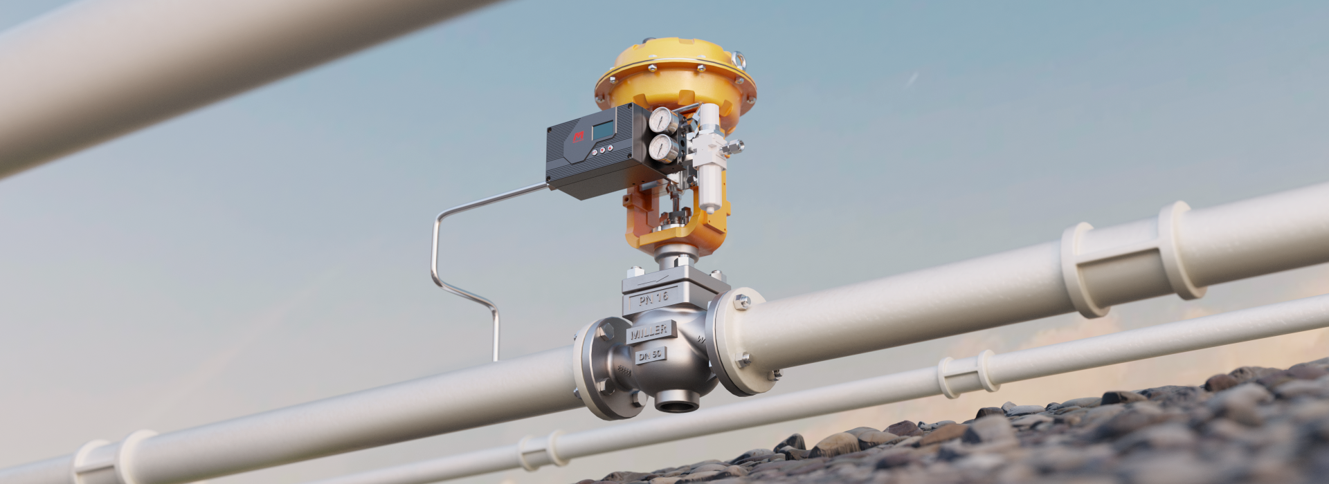
Use a pressure-reducing valve that recognizes two-phase flow.This is where Miller's P25 steam pressure reducing valve is interesting — it's specifically described as separating steam and condensate phases and discharging condensate while blocking steam pass-through, which directly targets the slug-formation problem rather than just regulating downstream pressure.
The flip side of both erosion and water hammer is steam loss. A failed trap blows live steam continuously, and that's usually the single largest heat-efficiency loss in a plant. Reliable traps don't just protect hardware; they pay for themselves.
Steam quality: superheat, dryness, and the noise problem
Two properties of the steam itself change what a valve experiences.
Superheat raises metal temperature beyond the saturation value, which is what drives creep. It also changes volume flow and therefore velocity through a fixed trim area — a valve sized for saturated steam may be badly oversized (or undersized) once superheat is accounted for.
Dryness fraction determines how much liquid is in the flow. Standard control valve sizing practice (the IEC 60534 series) covers the underlying equations, but the practical trap is that many sizing exercises assume dry saturated steam and never revisit the assumption.
Then there's noise and vibration. High-pressure steam valves are classic noise sources. Aerodynamic noise above roughly 85 dBA at 1 metre is not just a workplace-safety issue — high acoustic energy couples into the trim and piping and drives fatigue cracking. The IEC 60534 series includes a dedicated noise-prediction methodology for exactly this reason. Where noise is severe, a multi-stage or low-noise trim isn't a luxury; it's a mechanical-integrity measure.
What goes wrong in the cold part of the valve
Everything above is about the hot side. But a high-temperature steam valve also has a cold side — packing, actuator, positioner, and yoke — and that's frequently where the first failure appears.
The reason is the temperature gradient. Heat conducts up the stem from 400 °C at the plug to maybe 60 °C at the packing box. That gradient means:
-
The stem is longer and slightly conical in its hot condition.
-
Packing friction is highest where temperature is lowest.
-
Any actuator thrust calculation based on a room-temperature friction coefficient is optimistic.
Bellows-sealed designs address part of this by eliminating the dynamic stem seal entirely. The KBC10P pneumatic bellows control valve uses a multi-layer 316L stainless steel bellows, rated from −196 °C to 550 °C with leakage classifications per ANSI Class IV, V, or VI, ±0.1% control accuracy, and actuator supply pressure of 200–400 kPa. For steam service, that bellows does double duty: it removes fugitive emissions at the stem and keeps the actuator's thermal exposure lower, because there's no packing box breathing hot vapour.
Whether you need a bellows is a function of what the steam costs and how much leakage is tolerable — not a default. But on high-temperature lines where the packing has failed twice in three years, it's worth pricing.
Where the traps and filters belong in this conversation
Two components deserve explicit mention because they determine whether the valve upstream lives or dies.
Steam traps. Miller's DVG10 covers DN15 to DN25, PN25, with a working pressure range of 0.05 to 1.6 MPa and a rated condition of 400 °C at 1.57 MPa. Body materials span carbon steel (A105/WCB) through 304/CF8 and 316/CF8M, with flange, threaded, or welded connections. What matters for reliability is not the model number but the discipline around it: a trap that fails closed creates water hammer and erosion; a trap that fails open blows steam and costs money every hour.
Strainers. Particulate in steam is a real problem — mill scale from new pipework, welding slag, oxide from upstream components. A strainer upstream of a pressure-reducing valve or trap protects the small internal clearances those devices depend on.
Miller's FY steam strainer ranges from NPS 1/2" to 40" (DN15 to DN1000), pressure class 1.0 MPa to 16 MPa, in 304/CF8, 316/CF8M, or 316L/CF3M, with flow capacity from 15 kg/h to 30,000 kg/h and filtration from 5 to 25 microns. It's built to GB/T 14382-2008 (Tee strainers for fluids for pipes) and SH/T 3411-1999, with pressure testing per GB/T 13927-2008 — note that the current edition of that test standard is GB/T 13927-2022, so if you're writing a purchase specification today, cite the 2022 version.
Consistency check worth doing: a strainer rated to 25 microns will not protect a trap whose pilot orifice is 2 mm. Match the filtration level to the smallest downstream clearance, not to a habit.
Putting numbers on a real high-temperature package
Here's how the pieces look when you write them down against their actual published limits. This isn't a selection guide — it's what "the numbers behind the claim" look like in high-temperature steam service.
| Component | Model | Key limits | Service temperature |
|---|---|---|---|
| Steam trap | DVG10 | PN25, 0.05–1.6 MPa, DN15–DN25 | up to 400 °C at 1.57 MPa |
| Pressure-reducing valve | P25 | DN15–DN150, 1.0–2.5 MPa, 500 kg/h, ±1% accuracy, 10:1 turndown | saturated steam |
| Steam strainer | FY | DN15–DN1000, 1.0–16 MPa, 5–25 μm, 15–30,000 kg/h | steam service |
| Bellows control valve | KBC10P | DN15–DN600, Class 150–600, leak class IV/V/VI, ±0.1% | −196 °C to 550 °C |
Read that table as a set of constraints, not features. The P25 is a saturated-steam device — put it on a 400 °C superheated header and you're outside its stated medium. The DVG10's 400 °C rating applies at 1.57 MPa, not at its full PN25 rating; pressure and temperature trade against each other on the same curve. The KBC10P covers the widest temperature span, which is exactly what you'd expect from a bellows design with a full metal pressure boundary.
This is the discipline that separates a valve that lasts fifteen years from one that gets replaced at year three: read the rating as a curve, and check which end of it your process sits on.
What to actually verify before the valve ships
If you take one thing from this article, take this list. It's short, and each item has a paper trail.
-
The material grade, not just the family. "Stainless steel" is not a specification. CF8, CF8M, CF3M, and CF8C behave very differently at 500 °C.
-
The pressure-temperature curve for the actual material. Cite ASME B16.34 or the relevant product standard, and confirm the valve's rated pressure at your operating temperature.
-
The test standard and the actual record. API 598 or GB/T 13927-2022, with the test pressure and duration recorded.
-
Hardfacing specification on seats and trim. CoCr alloy, hardened stainless, or bare? This determines erosion life.
-
Packing or bellows details, and the stem temperature at the packing. If the vendor hasn't calculated it, they haven't thought about the cold end.
-
Actuator thrust at temperature, not at ambient. Friction coefficients and spring rates both drift with heat.
-
A written heat-up rate limit. If it isn't in the installation instructions, ask for it in writing.
The honest summary
High-temperature steam is one of the few services where the system matters more than the component. A perfectly specified valve in a line with a failed trap and a cold, fast start-up will fail — and it will fail in a way that looks like a valve defect, which makes it very hard to diagnose after the fact.
The failure mechanisms are not mysterious. Metal creeps above a temperature threshold that depends on the alloy. Castings contain porosity that testing may or may not reveal. Wet steam erodes at a rate proportional to the cube of velocity. Thermal cycling relaxes bolted joints and initiates fatigue at discontinuities. Water hammer converts a condensate slug into a pressure wave in milliseconds.
None of those are exotic. All of them are managed by specifying materials against a temperature curve rather than a pressure number, controlling heat-up rate, keeping steam dry, and requiring documentation rather than assurances.
Do those four things and the valve becomes what it should be: the boring part of the system.
Sources and standards referenced
-
ASME B16.34 — Valves: Flanged, Threaded, and Welding End (pressure-temperature ratings)
-
ASME B16.5 — Pipe Flanges and Flanged Fittings
-
ASME B31.1 / B31.3 — Power Piping / Process Piping
-
ASME BPVC Section II — Materials (including the elevated-temperature property tables behind creep-limited ratings)
-
API 598 — Valve Inspection and Testing
-
IEC 60534 series — Industrial-process control valves (sizing equations and noise prediction)
-
GB/T 13927-2022 — Industrial valves — Pressure testing (current edition; supersedes GB/T 13927-2008)
-
GB/T 14382-2008 — Tee strainers for fluids for pipes (current edition; supersedes GB/T 14382-1993)
You can also pick products which fit for your pipe lines on the Miller vlave selection center
Product ratings quoted here are as published by the manufacturer. Always confirm the applicable material grade, pressure-temperature curve, and test documentation against your specific process conditions before specifying.A note on what this article is and isn't. It's a field-oriented explanation of why steam valves fail in high-temperature service and what the governing standards say. It isn't a substitute for a sizing calculation against your actual steam conditions — flow rate, pressure drop, superheat, and dryness fraction all change the answer, and none of them can be guessed from a product table.
reviewed by Su Gong, with 20 years of field commissioning experience on valve systems.